Energy Storage (Battery)
The Energy Storage component (often referred to simply as the Battery) is an essential part of modeling modern, resilient electrical systems. It allows you to buffer energy—storing excess power produced by your renewable generators (like solar or wind) or drawn from the grid during off-peak hours, and discharging it to power your hydraulic pumps when demand is high or grid costs peak.

UI Workflow and Configuration
To add an Energy Storage unit to your model, select the battery icon from the Component Toolbar and drag it onto the canvas.
Once placed on the canvas, the battery node displays a dynamic visual indicator of its State of Charge (SOC) during an active simulation.
Double-click or right-click the node and select Properties to open its configuration dialog.

Key Properties
- Component ID: A unique string identifier for the battery (e.g.,
Battery_A). - Capacity (kWh): The total physical energy storage capacity.
- Initial SOC (%): The State of Charge at the start of the simulation.
- Max Charge (kW): The maximum rate at which the battery can absorb power.
- Max Discharge (kW): The maximum rate at which the battery can supply power.
- Efficiency (%): The round-trip electrical efficiency (accounting for losses during charging and discharging).
- Min SOC Limit (%): The lowest acceptable charge level. The battery will refuse to discharge below this point to prevent deep-cycling damage.
- CC/CV Transition SOC (%): The Constant Current / Constant Voltage transition point. Above this SOC percentage, the battery's charge acceptance rate tapers off (slows down) as it approaches 100% full.
[!WARNING] Power Rate Limitations and Pump Startup R-THYM strictly enforces the physical constraints of the battery. If your system attempts to charge or discharge the battery at a rate exceeding the Max Charge (kW) or Max Discharge (kW), a telemetry warning will be triggered, and the actual power flow will be "clipped" (hard limited) to that maximum amount.
Critical Impact: This limitation can cause a downstream pump to fail to turn on. Pumps often require a significant surge of power at startup to overcome initial static head and inertia. If the battery's Max Discharge rate is lower than the pump's startup power requirement, the pump will experience power starvation and will remain off.
Power Connectivity
To utilize the battery, you must connect it to other components using Power Links.
- To Charge: Route a Power Link from a Utility Grid or a Power Generator to the Battery.
- To Discharge: Route a Power Link from the Battery to a Pump or the Utility Grid (if exporting).
Note: You can connect multiple sources to a single battery simultaneously.

Live Telemetry
Left-clicking an Energy Storage node on the canvas reveals its performance data in the right-hand Telemetry Panel.
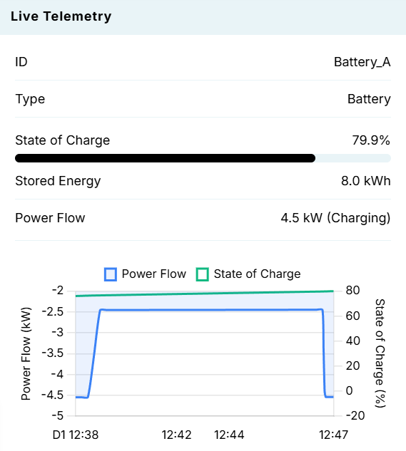
The panel tracks:
- State of Charge: Displays the real-time SOC percentage alongside a visual progress bar.
- Stored Energy: The absolute volume of energy currently stored in the battery (in kWh).
- Power Flow: The instantaneous rate of power moving in or out (in kW), along with the active state (Charging, Discharging, or Idle).
- Dynamic Charts: Visualizes the Power Flow alongside the State of Charge over time. In the screenshot above, you can clearly see a constant charging flow driving a slow, steady increase in the State of Charge curve.
