Deadband Control Links
In water distribution and electrical systems, many actuators operate in a binary state—either fully open/closed or fully ON/OFF. Deadband Control (also known as hysteresis control or two-position control) is the standard method for managing these binary states based on sensor telemetry.

This guide explains how R-THYM simulates state-based control and how to configure deadband buffers to prevent equipment damage and solver instability.
The Physics of Hysteresis
Without hysteresis, a controller reacts to a single setpoint. For example, if a pump is programmed to turn ON when a tank drops below 10 ft:
- The level drops to 9.99 ft, and the pump turns ON.
- Immediately, the pump discharges water, raising the level to 10.01 ft.
- The controller sees the level is above 10 ft and turns the pump OFF.
- The level drops back to 9.99 ft, and the pump turns ON again.
This rapid, repetitive toggling is called short-cycling. In physical systems, short-cycling causes extreme wear on motor starters, overheats windages, and damages check valves. In numerical simulations, it causes the hydraulic solver to struggle to converge, leading to numerical oscillation.
R-THYM solves this by implementing a Deadband Buffer centered around the target setpoint.
Mathematical Logic
A deadband control link defines an active band of width $D$ around a target setpoint $T$. The actual activation and deactivation thresholds are split into a lower threshold ($T_\text{low}$) and an upper threshold ($T_\text{high}$):
$$T_\text{low} = T - \frac{D}{2}$$ $$T_\text{high} = T + \frac{D}{2}$$The behavior depends on whether the control action is configured to Fill (increase the monitored variable) or Drain (decrease the monitored variable).
1. Fill Action (e.g., Tank Supply Pump)
A fill action operates when the monitored variable is too low. The pump or valve stays in its current state until it crosses the boundary limits:
- Turn ON condition: The monitored value drops below the lower threshold: $$Value < T_\text{low}$$
- Turn OFF condition: The monitored value rises above the upper threshold: $$Value > T_\text{high}$$
- Hysteresis Zone: When the value is inside the buffer ($T_\text{low} \le Value \le T_\text{high}$), the component retains its previous state (latched).
         Value Decreasing ──> (Pump Turns ON at T_low)
   ──[───|───────────────────|───]──
        T_low     Target    T_high
         Value Increasing ──> (Pump Turns OFF at T_high)
2. Drain Action (e.g., Tank Outflow Control Valve)
A drain action operates when the monitored variable is too high:
- Turn ON condition: The monitored value rises above the upper threshold: $$Value > T_\text{high}$$
- Turn OFF condition: The monitored value drops below the lower threshold: $$Value < T_\text{low}$$
- Hysteresis Zone: When the value is inside the buffer, the component retains its previous state.
UI Configuration
When configuring a Control Link for Deadband mode, select Simple Control as the strategy and fill in the following parameters:
| Parameter | Description |
|---|---|
| Action Input | The control behavior (e.g., Turn ON when below target, Turn OFF when below target). |
| Target Value | The setpoint ($T$) representing the center of your control band. |
| Deadband Buffer | The total width ($D$) of the hysteresis region. |
[!WARNING] Setting the Deadband Buffer to
0disables hysteresis, turning the control link into a single-setpoint switch. This should only be done if the monitored variable is slow-moving and the simulation time step ($\Delta t$) is large enough that short-cycling is physically impossible.
Modeling Best Practices: Sizing the Deadband
To size a deadband buffer properly, consider the relationship between the tank's storage capacity, the pump's discharge rate, and the desired cycle time.
The time $t_\text{run}$ it takes to fill the buffer zone is governed by the net flow entering the tank ($Q_\text{net}$) and the tank cross-sectional area ($A$):
$$t_\text{run} = \frac{A \times D}{Q_\text{net}}$$Where: * $A = \frac{\pi \times d^2}{4}$ (with $d$ being the tank diameter). * $D$ is the deadband buffer height. * $Q_\text{net} = Q_\text{pump} - Q_\text{demand}$.
[!TIP] A good rule of thumb for water distribution models is to design the deadband $D$ such that the pump runs for at least 15 to 30 minutes per cycle. If you observe your simulation results and see a pump cycling multiple times per hour, increase the Deadband Buffer or increase the Tank's Diameter to add more damping capacity to the system.
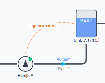
For comparison of deadband sizes, refer to the examples shown below. The first one uses a ±10% deadband.

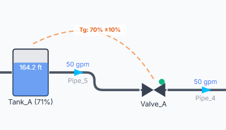
The second one uses a ±1% deadband.
