Power Switch
The Power Switch is a key control component in the R-THYM electrical and energy network simulation. Acting as a digital relay or circuit breaker, it allows you to dynamically or statically control the routing of electrical power through specific branches of your model.
Power Switches are critical for designing multi-source power topologies, such as hybrid microgrids. For example, you can use them to isolate solar arrays and battery banks, shed load during peak utility pricing periods, or simulate backup generator transfer switches.
UI Workflow and Configuration
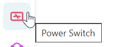
To add a Power Switch to your model, select the toggle switch icon from the Component Toolbar and drag it onto the canvas.
Properties and Parameters
To configure its parameters before running a simulation, double-click the node (or right-click and select Properties) to open the configuration dialog.

The Power Switch properties dialog allows you to define the following parameters:
- Component ID: The unique alphanumeric identifier for the switch (e.g.,
PowerSwitch_A). - Max Capacity (kW): The maximum amount of active power that can transmit through the switch at any given moment. During routing, the simulation balances active power shares based on link capacity constraints.
- Initial Status: The default state of the switch at the start of the simulation run.
- ON: The switch starts closed, allowing power to flow immediately.
- OFF: The switch starts open, blocking all electrical flow.
Simulation Behavior and Routing
During the simulation, R-THYM dynamically solves the power network routing based on the status of all nodes:
- State Verification: The solver checks the current active status (either the configured initial state or any real-time user overrides) to determine if the switch is closed (
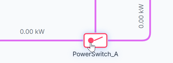
ON) or open (OFF). - Path Disconnection: If the switch is open (
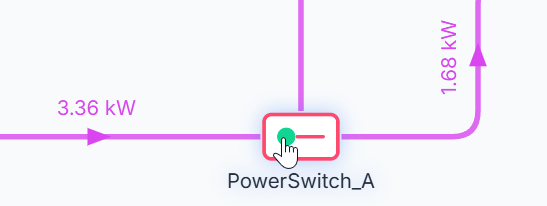
OFF), any electrical path traversing the switch is severed. Downstream loads (such as pumps or battery chargers) will not be able to draw power from upstream sources through this switch. - Flow Tracking: If the switch is closed (
ON), power flows through the switch. The real-time electrical flow (in kW) passing through the node is aggregated and tracked continuously for telemetry reporting.
[!NOTE] Like all R-THYM power connections, the Power Switch is bidirectional. Power can flow through the switch in either direction (e.g., importing power from the grid to run pumps, or exporting excess solar generation back through the switch to the Utility Grid).
Live Interaction (On-the-Fly Control)
R-THYM allows you to interact with Power Switches dynamically during an active simulation.
To manually toggle the switch:
- Locate the Power Switch on the canvas during a running simulation.
- Hover over the toggle icon and click directly on the status indicator dot (the green or red circle).
- The switch will instantly change its state (greed dot to red dot, or vice versa), and the solver will immediately update the electrical routing topology on the fly.
This feature is invaluable for testing emergency load-shedding procedures, manual grid-disconnection scenarios, and failure response plans.
Live Telemetry
Single-clicking a Power Switch on the canvas during a simulation reveals its real-time telemetry sidebar panel.
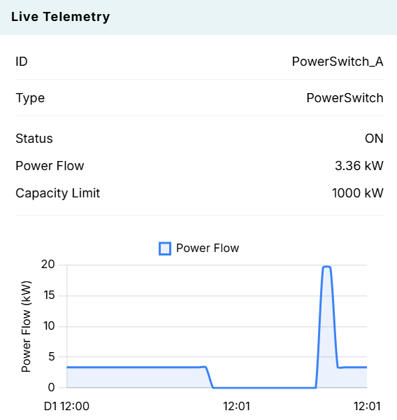
The telemetry panel tracks:
- ID: The unique component identifier.
- Type: The component type (
PowerSwitch). - Status: The current interactive status (
ONorOFF). - Power Flow: The instantaneous power (kW) passing through the switch.
- Capacity Limit: The maximum configured power capacity (kW).
- Dynamic Chart: A rolling chart that visualizes power flow (kW) over time. You will see the curve drop immediately to
0 kWwhen the switch is clicked open, and return to its load-carrying capacity when clicked closed.