Building the Delivery System
Now that we have defined our agricultural areas, we need to construct the hydraulic network that will deliver water to them. IAMDD uses an intelligent, map-based interface to automatically connect nodes and pipes.
The Network Drawing Tools

To build your network, you will primarily use the two lower tools in the left-hand drawing toolbar:
- Draw Pipe: Used to draw water mains, sub-mains, and laterals.
- Draw Junction: Used to place reservoirs, tanks, delivery points, and pipe routing corners.
1. Adding a Water Source (Reservoir)
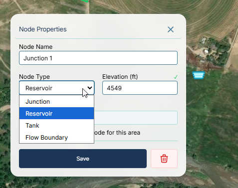
Every network requires at least one water source (an infinite-supply reservoir or a tank). 1. Click the Draw Junction tool in the left toolbar (it looks like a small dot with a circle). 2. Click on the map where your water source is located. 3. Switch back to the Pointer / Select Tool, and click on the node you just created. 4. In the right-hand Properties Panel, locate the Node Type dropdown and change it from Junction to Reservoir.
2. Placing Routing Junctions
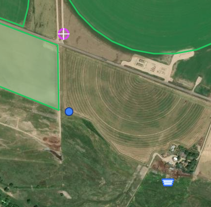
To route pipes around corners, roads, or elevation changes, you need routing junctions. 1. Use the Draw Junction tool to place points wherever your pipeline will bend or branch. 2. In the Properties Panel, you can manually set the ground elevation for each node, or allow the system to infer it from the topographic data.
3. Assigning Delivery Nodes to Areas
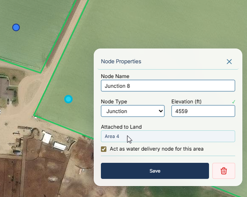
IAMDD automatically links water demand to a delivery point using spatial recognition. 1. Use the Draw Junction tool to place a single node directly inside the boundary of your agricultural area. 2. Because the node physically intersects the polygon, the engine automatically registers it as the delivery point for that field's crop water demand!
4. Drawing Pipes & Sizing
- Select the Draw Pipe tool (the jagged line icon) from the left toolbar.
- Click directly on your Reservoir to start the pipe, then click on your routing junctions sequentially, and double-click on your final Delivery Node to end the pipe.
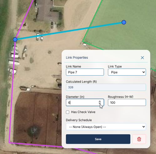
- Switch to the Pointer / Select Tool and click on a pipe segment.
- In the Properties Panel, enter the Diameter (inches) and Roughness coefficient.
5. Adding a Pump
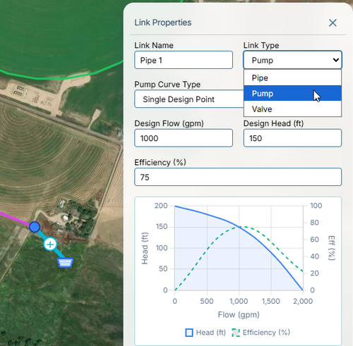
If your water source is not at a sufficiently high elevation to drive gravity flow, you will need a pump. 1. Select the pipe segment that immediately exits your water source. 2. In the Properties Panel, change the Link Type dropdown from Pipe to Pump. 3. The interface will immediately update to show pump parameters. Enter your desired Design Flow (gpm) and Design Head (ft) to generate a standard pump curve.
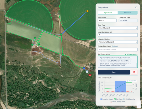
6. Running the Simulation & Viewing Results
With the network fully drawn, you are ready to solve the hydraulics! 1. Click the green Run Simulation button (Play icon) in the top menu bar. 2. The engine will calculate crop demands, generate delivery schedules, and run the hydraulic solver across the entire simulation period. 3. Once complete, click on any Pipe to see flow and velocity plots in the side panel. 4. Click on any Node to view pressure trends. 5. Click on your Agricultural Area to view the dynamic Soil Water balance and Irrigation Delivery Rate plots.