Building Your First Project
Welcome to the IAMDD platform. In this guide, we will walk through the foundational steps of creating a new project, navigating the map, and defining agricultural demand areas using interactive GIS tools.
1. Creating a New Project
To begin a clean simulation environment, follow these steps:
- In the top navigation bar, click File -> New. This will clear any existing data from your workspace.
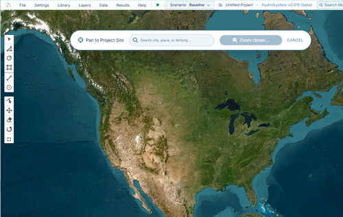
- Using your mouse wheel to zoom and clicking and dragging to pan, navigate the map to your region of interest. Alternatively, you can enter a place name or latitude and longitude coordinates to jump to a location.
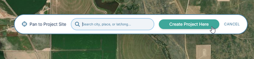
- Once you've located your site, click "Create Project Here".
- Save your project and give it a name. Click File -> Save, enter a name for your project, and confirm. Your project is now stored in your account.
2. Defining Agricultural Areas
Water demand in Hydro-System is driven by the physical areas you define on the map. The platform provides three primary drawing tools located on the left-side toolbar to outline these regions:

- Polygon Tool: Click to place individual vertices around complex, irregular field boundaries. Connect to the first point to close and complete the polygon.
- Rectangle Tool: Click and drag to quickly define square or rectangular plots. Note you can rotate these after initialization.
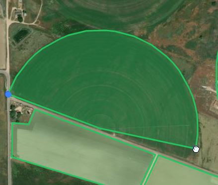
- Circle Tool: Click at the center of your pivot and drag outward to define the radius of a center-pivot irrigated field. Click and drag the blue node at the top to create partial circles.
3. Configuring Area Properties
When you draw an area, Hydro-System automatically queries external USDA databases to evaluate the underlying soil and crop composition. Clicking on a drawn area will open the Properties Panel on the right side of the screen, displaying the following inputs:
- Area Name:
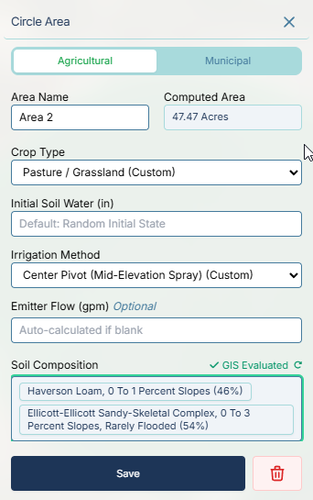 The identifier for the field (e.g., Area 1). You can rename this to match your operational zones.
 - Computed Area: Automatically calculated based on your drawn geometry (e.g., 134.51 Acres).
- Crop Type: A dropdown populated with local crop data. You can manually select a different crop (e.g., Alfalfa).
- Initial Soil Water (in): Sets the starting moisture level for the simulation. By default, this is set to Random Initial State to simulate realistic, non-uniform starting conditions across multiple fields.
- Irrigation Method: Defines the delivery hardware (e.g., CenterPivotImpact (Custom)), which affects application efficiency.
- Emitter Flow (gpm): An optional input to hardcode the hydraulic demand of the field. If left blank, the engine will auto-calculate the required flow based on ET demand and system capacity.
- Soil Composition: A read-only list of the soil profiles automatically evaluated via GIS for your drawn shape (e.g., Valent Sand, 0 To 3 Percent Slopes (6%), Ellicott-Ellicott Sandy-Skeletal Complex).
4. Modifying Drawn Areas
Ag-boundaries often need minor adjustments. You don't need to redraw a field if you make a mistake; instead, use the modification tools on the left-side toolbar:
- Edit Layers:
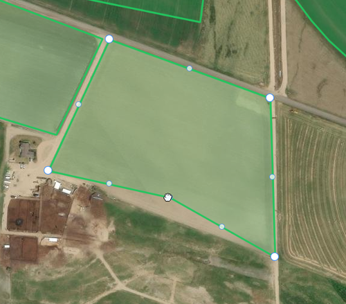 Click this tool, then click on a shape to reveal its vertices. You can drag individual points to reshape the boundary.
 - Move Layers: Select this tool to click and drag an entire shape to a new location without altering its dimensions.
- Rotate Layers: Select this tool, click on a shape, and drag the rotation handle to spin the field geometry—particularly useful for aligning rectangular plots.
Now that your agricultural areas are defined and generating water demand, the next tutorial will cover connecting these fields to a hydraulic delivery network using pipes and pumps.