Hydraulic Nodes
Nodes represent the point-connections within your hydraulic pipe network. Whenever you drop a node on the map, IAMDD automatically queries the USGS 3D Elevation Program (3DEP) to determine the exact ground elevation at that coordinate. Accurate elevations are critical, as they dictate the static pressure head throughout your system. (Note: You can always manually override this elevation in the Properties Panel if you have better survey data).
There are four types of nodes available in IAMDD, which can be toggled via the Node Type dropdown:
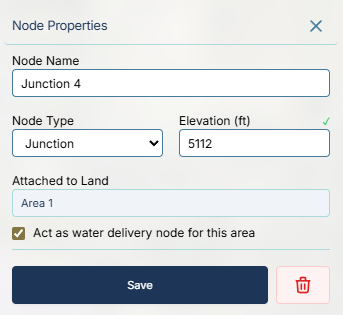
1. Junctions
Junctions are the standard, default node type. They serve two primary purposes:
- Routing: Connecting two or more pipes together, or routing a single pipe around a sharp corner.
- Delivery Points: If you drop a junction inside (or near) a demand Area polygon, you can check the box for "Act as water delivery node for this area". The engine will extract water from the pipe network at this exact junction to satisfy the area's calculated demand, simulating the field's headgate or a neighborhood's main tap.
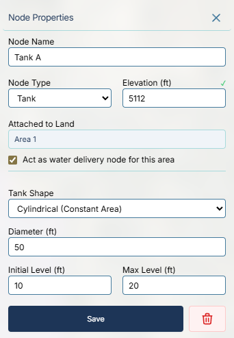
2. Tanks
Tanks represent finite-volume storage facilities (e.g., elevated water towers, cylindrical ground storage tanks, or excavated ponds).
- Their internal water level fluctuates dynamically during the simulation based on the balance of water entering and leaving.
- You must configure the physical dimensions of the tank. You can select a standard Cylindrical shape and input the diameter, or select Library Curve to apply a custom Depth-to-Volume relationship for irregular shapes.
- You must define the Initial Level (how full it is when the simulation starts) and the Max Level (the overflow limit).
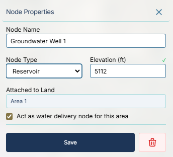
3. Reservoirs
Reservoirs represent an infinite source of water, such as a massive natural lake, a primary river diversion, or a connection to a larger municipal grid.
- Unlike tanks, a reservoir's water elevation (Hydraulic Grade Line) remains completely fixed regardless of how much water you pull from it.
- Every hydraulic simulation requires at least one Reservoir or Tank to act as the primary water source.
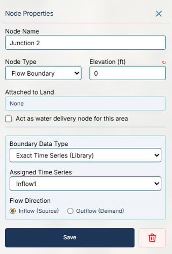
4. Flow Boundaries
Flow Boundaries are special nodes used to force a specific flow rate into or out of the pipe network, ignoring standard demand calculations.
- Instead of acting like a passive demand area, a Flow Boundary is driven by the Time Series Library or the Patterns Library.
- Inflow (Source): Injects water into the system (e.g., simulating a variable groundwater well or a booster pump station).
- Outflow (Demand): Extracts water from the system (e.g., simulating a massive pipeline leak or a bulk water sale to a neighboring district).